Intrinsics are calibrated using a set of chart images, the
extrinsics using an sequence of wand images and the coordinate frame is
defined using a set of floor markers. Intrinsics need only be
calibrated once for a given camera configuration, so the chart images
need only be captured and processed once. Calibrate the extrinsics
before each capture session, this refines the estimated intrinsics
and recalculates the position and orientation for each camera.
That way you can account for any changes in intrinsics over time and
any camera movement for example if a cable or rail is knocked. You will
need to capture a wand sequence and the floor markers before each
capture session. Define a directory structure for you data to
store and extract the images, for example for a vba capture with
capture sessions performed on a daily basis you might use:
/vol/v/capture1/vba/calibration/chart
/vol/v/capture1/vba/2006-02-13/calibration/floor
/vol/v/capture1/vba/2006-02-13/calibration/wand
Calibrating Intrinsics
To calibrate the intrinsics you will need to capture around 10 chart images per camera in the configuration.
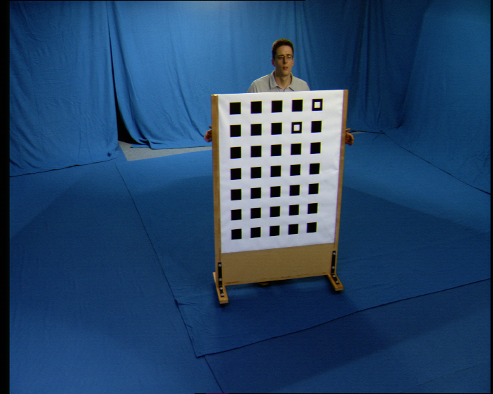
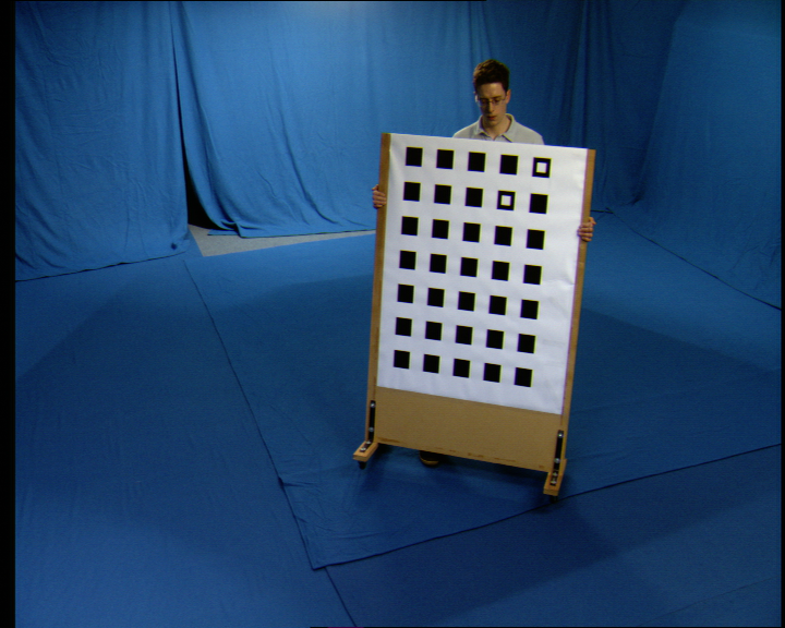
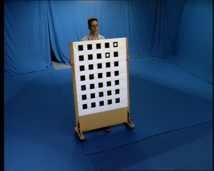
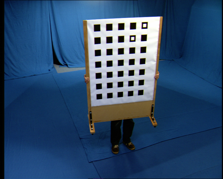
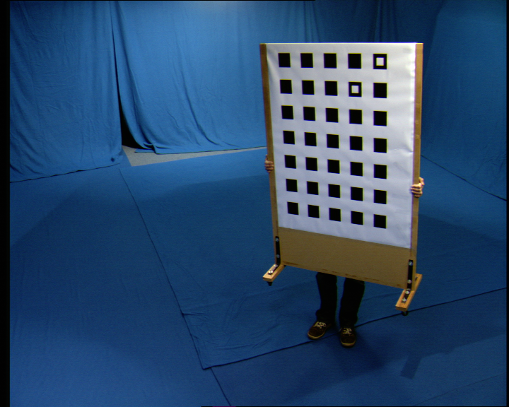
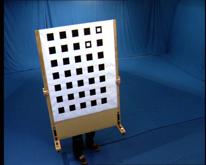
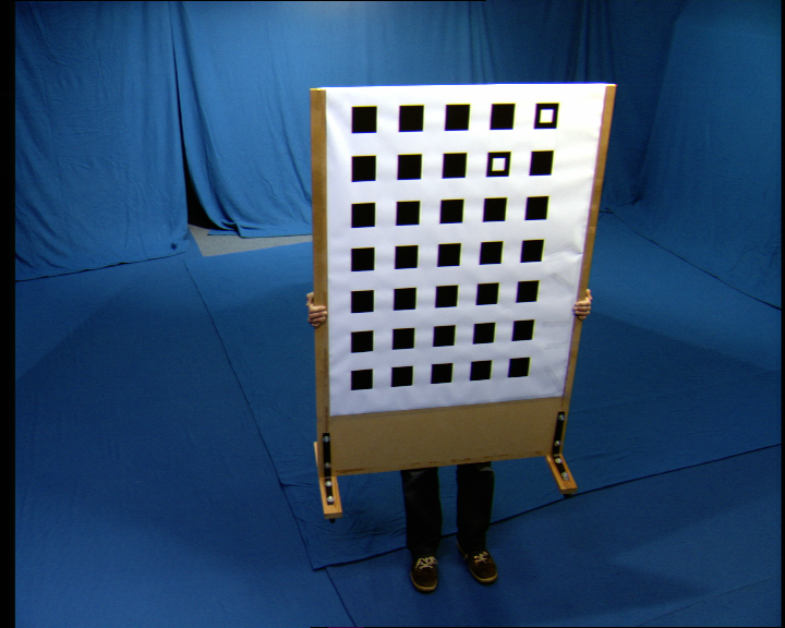
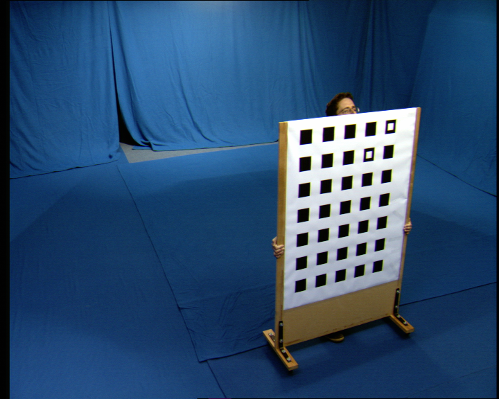
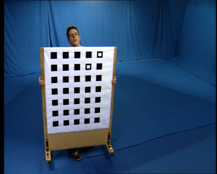
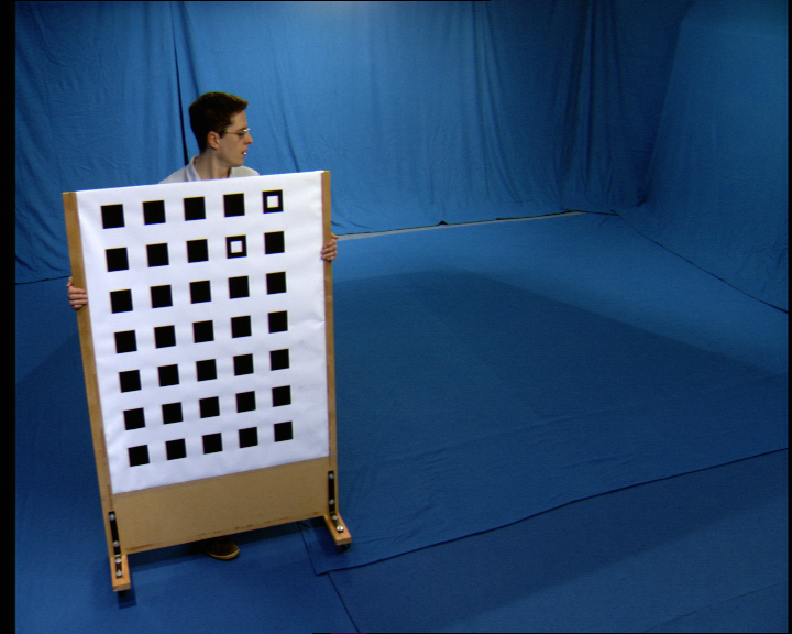
You can speed up the process by grabbing the chart from adjacent
cameras using the grab2 script. For example to grab 10 frames at 5
second intervals starting in 15 seconds as capture number 0 for cameras
0+1, then 2+3, then 3+4, use:
grab2.csh 00:50:00 00:15:00 125 0 1 0
grab2.csh 00:50:00 00:15:00 125 2 3 0
grab2.csh 00:50:00 00:15:00 125 3 4 0
Move the capture to the storage array and extract the images.
moveall.csh 0 /vol/v/capture1/2006-02-13/calibration/chart
extractall.csh 0 /vol/v/capture1/2006-02-13/calibration/chart
Run the intrinsics calibration tool on the extracted images. The
binary can be built from the Cvssp3D repository under
Applications/StudioTools/CalibrateIntrinics. This also contains the
chart image chart/Chart.png and coordinate file chart/Chart.coords
needed by the application. From the location where the chart images are
extracted use:
CalibrateIntrinsics -i grab.%d.%05d.png -c Chart.png -co
Chart.coords -n # -v (where # is the number of cameras)
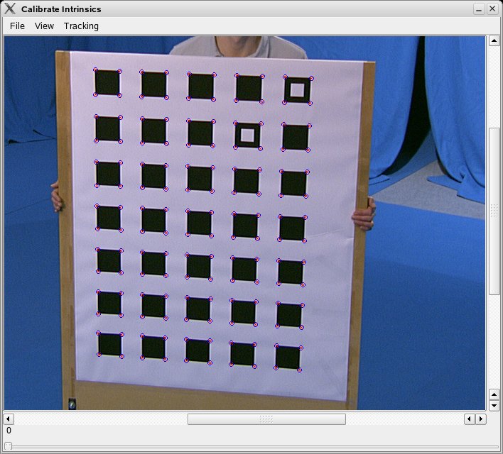
You can switch cameras from the View menu. First select a camera,
then select from the Tracking menu Track Chart to extract the chart for
each camera image. This process is multithreaded so you can switch
views and track another camera simultaneously. Once tracked, check the
result overlaid on each image as shown above and reject any frames
where tracking has failed. Then for each camera select Estimate
Intrinsics from the Tracking menu. This will estimate the central point
and focal length of the camera. The view menu will show a check against
each camera that has intrinsics estimated. Finally select Save from the
File menu to save all the estimated intrinsics in intrinsics.txt. The
file defines for each camera:
min_row max_row min_col max_col fx fy cx cy
NOTE: Estimation of the central point has been found to be unreliable and unnecessary so leave this switched off. The aspect ratio is fixed at 59:54 for the PAL SD images and 1:1 for the HD images.
Calibrating Extrinsics
Calibrate extrinsics using the wand technique before each capture session, this defines the position and orientation of the cameras and also optimises the intrinsics estimated from the charts. You will need to grab around 200+ frames of the wand in all camera views. Make sure to measure the distance between the markers on the wand as the distance is used to define the scaling, positioning the cameras in space. NOTE: make sure to hold the wand horizontally as well as vertically as this will improve the accuracy in scaling cameras positioned horizontally.
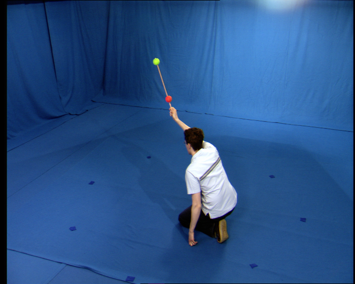
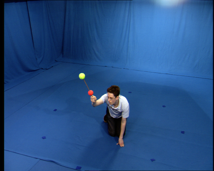
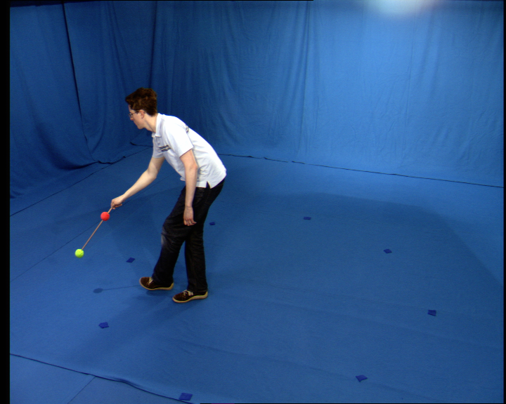
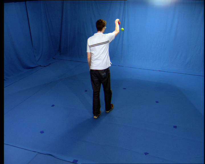
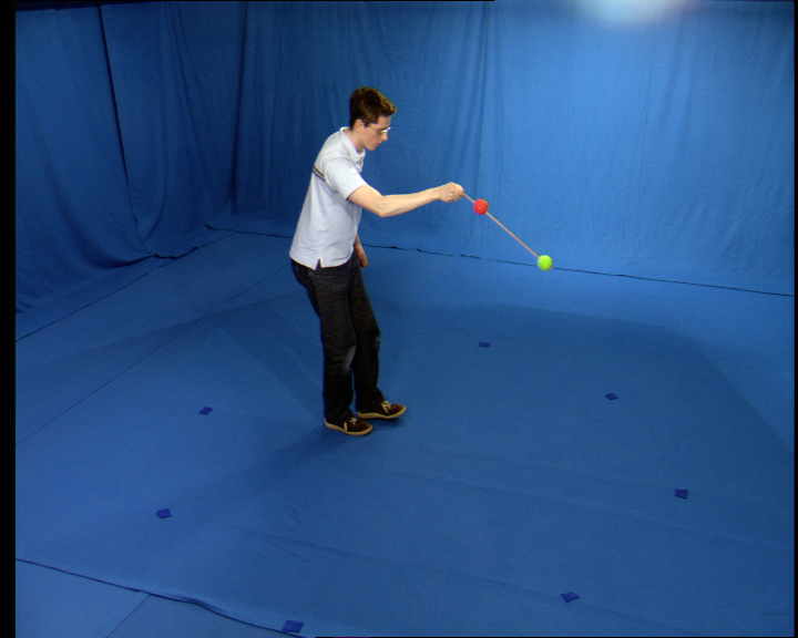
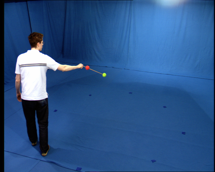
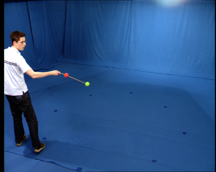
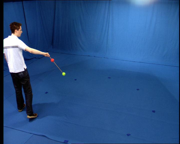
To grab 180 frames from all cameras at 2 second intervals starting
after a 15 second delay as capture 0, use:
graball.csh 06:00:00 00:15:00 50 0
Move the images to the storage array and extract all.
moveall.csh 0 /vol/v/capture1/2006-02-13/calibration/wand
extractall.csh 0 /vol/v/capture1/2006-02-13/calibration/wand
You will need to extract all the wand markers in the images to
perform the calibration. Use the ExtractWandMarkers tool from the
Cvssp3D repository under Applications/StudioTools/ExtractWandMarkers.
From the directory where the images are extracted use:
ExtractWandMarkers -i grab.%d.%05d.png -n # -v (where # is the
number of cameras)
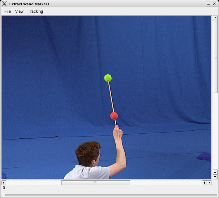
For each camera you will need to select the markers in one image to define the colour model for each marker and then track the markers through the image sequence. Select a camera from the View menu, from the Tracking menu select Select Markers and click first on the green marker then the red marker on the wand. The command line should report "Set Green Marker", "Set Red Marker" - if this fails choose another image using the slider and select the markers again. Tracking is multi-threaded so that you can track another camera simultaneously. Once tracked, you can review the result and reject any frames where tracking has failed although this should not be necessary. The View menu will display a check against all tracked views, once tracked select File, Save to save the marker positions for each camera to the corresponding file points.00.txt, points.01.txt etc.
Calibrate the extrinsics using the extracted wand marker
positions. From your wand directory use the CalibrateWand command line
tool, available from Applications/StudioTools/CalibrateWand. You will
have to provide the intrinsics generated by CalibrateIntrinsics and the
wandlength, the distance between the markers on the wand e.g 0.4m.
CalibrateWand -intrinsics intrinsics.txt -wandlength 0.4 -files
CalibrateWand estimates camera position plus orientation and then
optimises these together with focal length and first order lense
distortion. Look for a subpixel final RMS error, any higher than 1-2
pixels and there is a problem such as unsynchronised cameras. The tool
outputs calibration1.txt with the camera calibration suitable for
PinholeCameraArrayC in the Cvssp3D repository. The file has the
following format:
num_cameras distortion_order
(Camera 1)
min_row max_row min_col max_col
fx fy cx cy
distortion params
3x3 Rotation matrix R
3x1 translation t
(Such that a world point in the camera coordinate frame is
given by p' = Rp + t)
(Such that a project point for a perfect pinhole camera
with no distortion is u = fx* p'.x/p'.zworld point in the camera
coordinate frame is given by p' = Rp + t)
(Camera 2)...
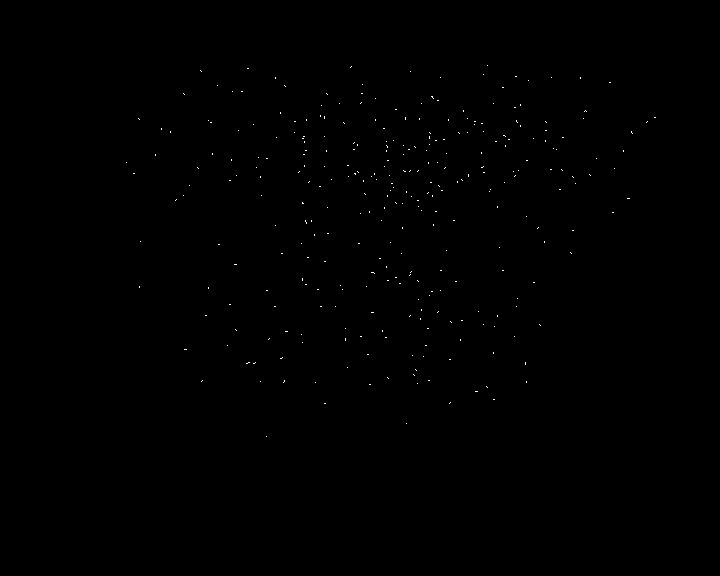
To assess the reconstruction accuracy use the tool WandError in the Cvssp3D repository under Applications/StudioTools/WandError. This tool reconstructs the 3D position of the wand markers and reports the RMS reprojection error +/- 2SD to the tracked position of the marker in the files points.00.txt, points.01.txt etc. Look for subpixel accuracy for a good calibration. The tool also outputs a pin diagram showing the error vector between the reprojection of the reconstructed points and the tracked position. This is useful to highlight any radial distortion seen as radially orientated error vectors. NOTE: if you see lots of seemingly randomly orientated error vectors more than a few pixels long you may have unsynchronised cameras.
Defining the world coordinate frame
The wand calibration places the world coordinate frame at the first camera. To create a useful coordinate frame positioned in the capture volume use RotateCalibration in the Cvssp3D repository under Applications/StudioTools/RotateCalibration. You will need to grab a single frame from all cameras with 3 floor markers to define the origin, x-axis and z-axis of the world coordinate frame, the y-axis will point vertically. Make sure it is easy to tell the difference between the x-axis and z-axis.
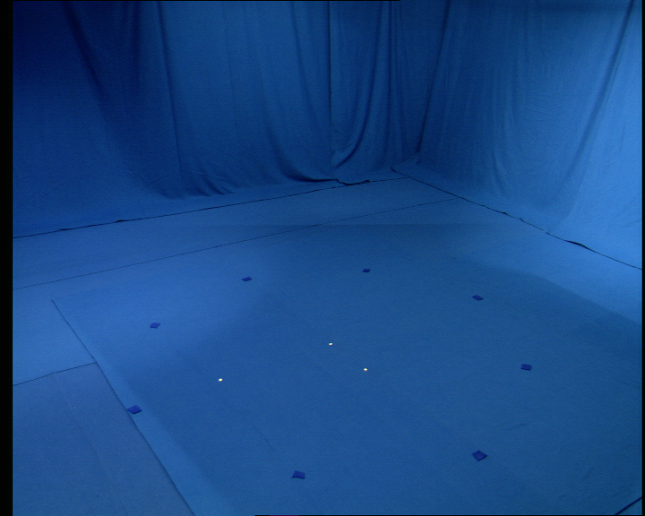
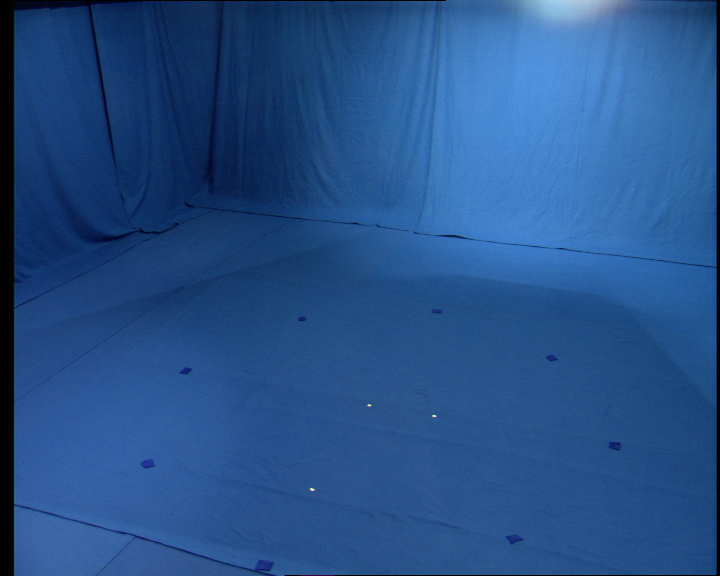
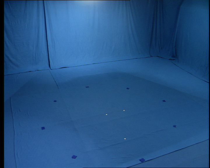
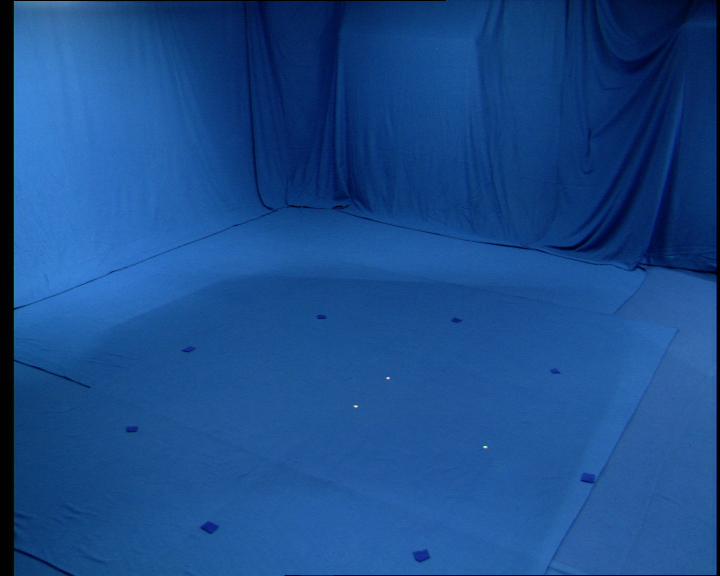
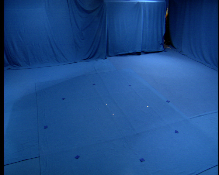
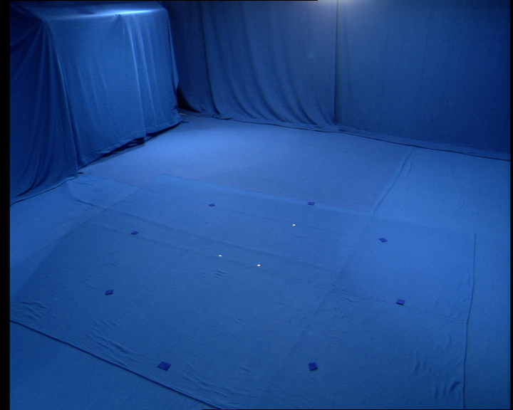
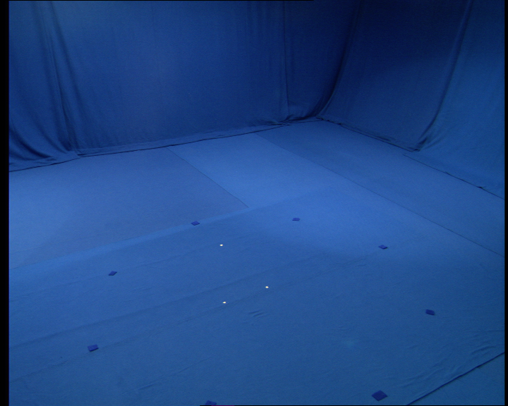
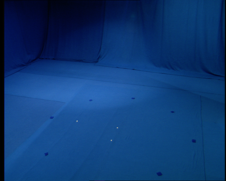
Grab a single frame, move to the storage array and extract the
images:
graball.csh 00:00:01 00:15:00 1 0
moveall.csh 0 /vol/v/capture1/2006-02-13/calibration/floor
extractall.csh 0 /vol/v/capture1/2006-02-13/calibration/floor
You will need to pass the floor marker images and the calibration
to RotateCalibration.
RotateCalibration -c calibration1.txt -i grab.%d.00000.png -v
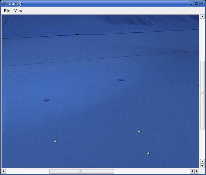
First select a view from the View menu then click on the origin, the x-axis and then the z-axis marker in the image. Make sure to select the markers in at least 3 images, preferably with orthogonal viewpoints then use File, Triangulate to triangulate the 3D position. Finally hit File, Rotate then File, Save to reposition and rotate the coordinate frame and save the new camera calibration.
Last modified: 12th November 2008